What can affect the water we drink, the air we breathe, the warmth and coolness that keeps us comfortable in winter and summer... What makes a building safe and livable? – Smart solutions for mechanical, electrical and plumbing systems (MEP) make our lives safer and more reliable.
How, when working on MEP systems, timed and properly planned procedures lead to the desired result, we will tell you about it consistently in our blog. Reducing costs, increasing energy efficiency and greater sustainability are all easier to achieve with expert advice.
At the first stage, we will need to prepare project documentation. This includes not only drawings and the standards to which the project is being built, but also estimates, costs and other important details. Projecting begins on the basis of the technical task provided by the customer. He must submit architectural drawings Complete package: Plans, cuts, facades, material specifications... as well as 41 expertise, complete technological drawings, lighting design and interior design.
Projecting consists of at least three stages: Concept-design, description of agreement on design principles and norms, general definitions.
Schematic design includes initial reports, determination of technical spaces and shafts, tracing of plans, layouts. The next stage is detailed design: preparation of detailed plans, reports, cuts, principle diagrams, specifications.
What we must have:
- Explanatory Note
- Source of drawings - table of contents
- Drawings - plans
- Principle schemes
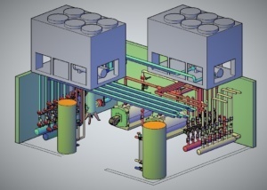
- Axonometric drawings
- General reports of the project
- Calculations of cables and circuit breakers
- Lighting calculations
- Main equipment specifications
- Material specification
Explanatory Note
To start working on the documentation, it is necessary to have a general explanatory card of the project. This is the verbal part of the drawings - the main message conveyed verbally. For example, calculations included in the project, review of systems, relevant standards, solutions and others. Although the explanatory card is the first in the list, it is created at the end of the project documentation, at the final stage. We can enrich the explanatory card with details and when describing a specific system or material, we can also attach photos for visualization.
Source of drawings - same table of contents
Along with the explanatory card, we should also have a source of drawings - a table of contents, where all the pages are numbered and named. This is so that a foreign eye can get to know the project in detail. A specific drawing may be assigned a corresponding code, and we can find the desired material according to the numbering.
Planning and Principle schemes
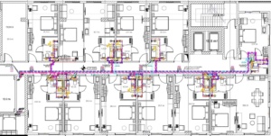
Planning is the engineering systems superimposed on architectural drawings. The third important part is the drawings, where the planning of all relevant systems is gathered. This includes both combined and separate plans (Mechanical-Electrical). For example, water supply, sewerage, ventilation, heating-cooling, electricity and weak currents - these 7 positions, which imply electro-mechanical solutions, should be both in the form of a single drawing and broken down separately. Every system has its own schematic diagram. When compiling them, it is important to consider how questionable it will be. For example, when a pipe is drawn, it should have an appropriate definition - with conditional designations and description of the material (diameter, cross-section, etc.). The principle drawing is the same planning in terms of content, in the given schematic view - we arrange the drawn plan in the scheme. In this case, the working principle of the system is clearly visible. If we have a hotel and a heating system, a similar type of drawing shows a single system working consistently on all floors, we can see the location of the chiller, boiler, wiring, etc. With a schematic drawing, we can easily read the project. As with planners, it is not necessary to mark specific pipe diameters here, it is enough to simply show the pipe. Every system has its own schematic diagram.
Axonometric drawings
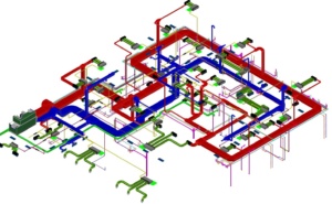
Axonometric drawings are created to better represent the visual side. For example, we can create a three-dimensional image and show some complex node of the system or cross-section several pipes for visibility. All projects have a similar drawing. It is created more for the naked eye, for example for the customer. As soon as you show the axonometric drawing, it will easily read the project.
General reports of the project
One of the necessary positions to start designing is the thermal technical report of the building, which means determining the heating-cooling energy required for the building. During the heat-technical report, the reports of all the partitioning structures of the building (external wall, floor, ceiling, glazing, etc.), their composition and the characteristics of the materials used should be taken into account. The mentioned report is important for determining the energy efficiency of the building, therefore it is of great importance for the selection of the main heating and cooling equipment and the rational use of the consumed energy.
We need hydraulic calculations To better select the device that should serve a specific system. For example, we should do similar work on water supply and fire systems. Let's take water supply hydraulics - in a residential building with 20 or 22 floors, we have to calculate all the details so that the residents of the last floors are not bothered by the lack of water pressure. If sufficient pressure does not reach the 20th floor, you install a water reservoir, set up a pump and create additional pressure with its help. All the processes are given in the system drawings - how the water enters the wells, how it goes to the customer through the pipes... all the pipes have their own pressure loss, you calculate all this and determine what performance pump will be needed in the mentioned building. It is important to choose the right equipment in order to insure against unnecessary expenses. Through hydraulic calculations in water supply, we create the desired pressure that we need at a given moment.
Along with water supply and sewage, hydraulic calculations are also made during the rainwater and drainage system. For example, when water overflows from the roof or when arranging drainage channels on the outer perimeter. In order not to flood the parking space (underground parking), it is necessary to arrange an emergency overflow system. During hydraulic calculations, we should take into account the location of the object and the frequency of rain. Considering the rainfall, we will need pipes of different diameters for the building in Tbilisi and Batumi.
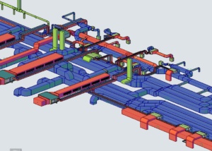
The principle of calculation is the same in the case of other engineering solutions, be it fire or heating-cooling systems. There is a similar procedure for ventilation, but if here we are dealing with water, there with the movement and exchange of air. Air sections, grilles, all articles are assembled in the project, and according to that, the hydraulic calculation is made. Then you select the desired device.
We do not need a hydraulic account in sewage systems, because it is a self-flowing system and creating pressure is not recommended. We use it only in rare cases - if there is no self-flow of water. We make a pump where the sewage mass collects and artificially create pressure.
Correct calculation of pipe diameters is important: how many floors are in the building, how many bathrooms are there, what is the number of residents... taking this into account, you prepare a report of pipe diameters in accordance with the standards. It is necessary to create pressure in the pipe About 60 to 80 percent be filled. You should also calculate the inclination of the pipe.
Calculations of cables and circuit breakers
Calculations of cables and automatic circuit breakers are necessary for proper and safe operation of the system.
 There are cables with different insulation, cross section and material. During the design period, if the cross-section of the cable is not selected correctly, the wire may overheat and melt, or we may lose voltage over a long distance and cause damage to the equipment. When calculating the cable, the distance and power should be taken into account in order to choose its cross-section.
Cables also differ in protective insulation. Cable insulation is selected based on where it runs and what is attached to it. In the event that the cable serves to feed fire systems, it is necessary to select a cable with fireproof insulation. If the cable is installed in the building, it must be non-halogen and low smoke, i.e. during combustion it should not release dense gas, only small smoke.
During the design period, the material of the cable should also be considered (it is made of aluminum and copper). It is mainly used during the design period Copper material, because it is a better conductor and, compared to aluminum, requires a smaller cross-section cable (although aluminum is much cheaper in terms of price). Basically, this material is agreed with the customer, taking into account his requirements.
Also, during the design period, the selection of the automatic circuit breaker must be taken into account. The main function of the automatic circuit breaker is to protect the cable from overloading and twisting.
Lighting calculations
Lighting calculations are also made during the project period, which actually represents the modulation of illumination in the dark part of the day and night. Such calculations help us to select the power of the lamps at the design stage in order to obtain the necessary illumination.
Main equipment specifications
Compiling the list of specifications for the main equipment is also an important step. It is easier for the contractor when there is a separate list of the main working equipment and a separate list of secondary materials and elements (pipes, elbows, etc.). For example, a chiller, AHU - Whether it is a ventilation unit or a pumping station, they need a detailed specification. When ordering equipment, the manufacturer asks you to provide information on a number of details: what is the internal and external temperature in the area where the equipment is used; What is the temperature of the water? What is the humidity in the working space and more. Such details must be adjusted and taken into account, which area will be served by the device. Humidity is one of the main criteria that should be written in the specification. The ventilation system must also mention the filtration system, because different spaces need different filtration.
Common Materials Specification
It is necessary to describe all the materials mentioned in the project. Be it pipes, air carriers, grilles or others. We should have the details of all of them spelled out and broken down. All system specifications should be broken down into separate lists. We write the characteristics, not a specific brand.
Preparation of project documentation is followed by no less necessary and important procedures... However, let's talk about the next steps in the next blog.
